
Guide for setting up a VARA FM gateway using a Motorola CDM750 UHF radio:
Background:
Originally, we used and Alinco dr-435t UHF radios and a Master's Communications DRA-50 sound interface device. Unfortunately, Alinco discontinued the dr-435t making an alternative required. , and although There plenty of other radios which easily interface for VARA FM, although quite expensive, we were concerned about saving club resources. After a great deal of research and discussion we settled on using a second-hand Motorola CDM-750 UHF radio along with the RIM-MAXTRAC USB (9600) sound interface card (www.repeater-builder.com/products/usb-rim-lite.html). Fortunately, there are still a number of CDM-750 radios available on eBay in the neighborhood of $130.00, which beats the Alinco price (when available) of $250.00 +, or any others for that matter. Also, the Repeater Builders RIM card was $50.00 rather than $110.00 for the DRA-50. The DRA-50 could be used with the Motorola, but you would have to make up the appropriate cable for interfacing. The RIM card is a simple plug-n-play (see Hardware Setup below). The Alinco is extremely easy to set up without the need for programming software. The Motorola requires its own proprietary software
which can be a pain in the A.. to find. Not to worry. I have a link to it in Software and Configuration section below.
There is an incredible amount of information regarding these CDM radios on Repeater-Builder.com. Actually, we've borrowed quite a bit from them... phenomenal resource.
Hardware Setup:
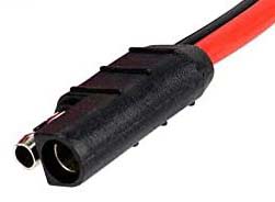
First thing to pay attention to when purchasing the Motorola CDM-750 is the frequency range. Our UHF gateway radio is version/part number AAM25RHC9AA1AN. Make sure it is in the HAM UHF band (or VHF if going that way, which is different number) and NOT in the bands above or below it. *** IMPORTANT--- please see Additional Information regarding using "Out of Band CDM-750 Radios" *** Doesn't matter if it comes with a microphone. You won't be using it anyway. You will need to locate an appropriate power connector if it didn't come with the radio. They are available on eBay and Amazon.
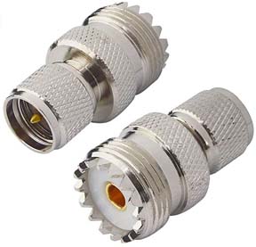
Also, the antenna connector is a mini-UHF. We obtained an adapter Mini UHF Male to UHF Female SO239 PL259. These are available on Amazon for very cheap. Ham Radio Outlet also carries them. There a number of other configurations, but the CDM radio has a Mini UHF Female connector. We found this to be the most convenient.
The sound interface card is purchased directly from Repeater-Builder.com. The one you want to use is the RIM-Maxtrac 9600 which currently sells for $50.00 and included the USB cable required to connect to your computer. They plug directly into the Accessory Connector on the back of the CDM radios.
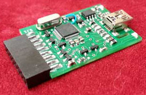
Click HERE to go to the Repeater-Builder.com. site for these units. They are simple plug-and-play interfaces requiring no jumper or pot settings. All adjustments are performed with you computer sound settings (see Software and Configuration below). It is also important to note the RIM card has the Accessory Connector pins 7 (Ground) and 9 (Emergency Wake-up) shorted together. The purpose of this is so that the CDM radio will automatically turn back on in the event of a power failure. That means you don't have to press the POWER button every time powers goes out. The importance is obvious for a Gateway. RB (Repeater-Builder) supplies the mini-USB to USB interface cable with the RIM card.
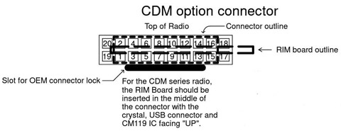
Please note the POSITION and ORIENTATION of the RIM card to the CDM Accessory Connector. Insert the card with components UP and the RIM connector in the CENTER of the Accessory Connector. The RIM board PCB will be off-center, but the CONNECTOR is in the center.
Software and Configuration
First thing you will want to do is to set up the software configuration and Code Plug for the CDM radio.
Before that you will need to obtain a programming cable. If you have unlimited funds you could purchase an official programming cable from Motorola. Good luck! There are, however, a number of sites selling third party programming cables, but ONLY ONE which actually works. I do not suggest you purchase a cable from China or other similar cables found on eBay or Amazon. Most of the time you will be throwing your money away. We purchase ALL our cables from Mark Dunkle (KJ6ZWL) at BlueMax49ers.com. He has the most reliable cables for ANY application. He does sell on eBay and Amazon, so you can go that route if you choose. You can usually purchase from his website as well.
You will also need to acquire the programming software, or better know as the CPS (Customer Programming Software) and install it on your computer. You may also be able to find a Motorola dealer who, usually for a fee, can program your radio for you. The latest version of the CPS which allows WIDE band is version R06.12.05. All the later versions only allow programming NARROW band, which is somewhat useless if you want a WIDE band gateway. The latest version of Microsoft Windows this will run on is XP. It is my understanding it will also operate with later versions of Windows, but only in native 32 bit mode (I have never tested it,so don't know for sure).Fortunately, most HAMS still have an XP machine tucked away somewhere. If you don't, find one, or you're out of luck. Version R06.12.05 can be downloaded as a .ZIP from HERE. Simply unzip it and install using Setup.exe.
The CPS will operate without the radio attached, so you can begin the programming without attachment if you choose (why??). Otherwise, insert the programming cable into the MIC connector on the front of the radio and the other end into a USB connector on your computer. I would recommend NOT attaching the RIM at this point. You will need to press the POWER button (on the VOLUME control) to activate the radio. If you attached the RIM, it MAY turn on automatically if the radio was previously programmed to do so. Otherwise, you will be programming it to do so after the RIM is attached.
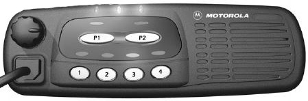
The POWER button / VOLUME control are on the upper left of the front (fairly obvious). Most likely, the LED above the button marked "1" will be lit. That means frequency channel "1" is active (doesn't mean transmitting, just the ACTIVE channel). If any of the other LEDs above "2, 3, 4" are lit then that channel is active. "P1" and "P2" buttons are programmable and you won't be using them. You most likely will also not be using buttons "2", "3", or "4" since those simply change channels and, being a VARA FM gateway, only need a single channel which defaults to "1" on startup.
Setting up the Motorola CPS ver. R06.12.05
You do not need to have the radio connected to the programming cable to set up the CPS. You can either create a new CodePlug by Clicking File -> New, or download the existing CodePlug from the radio (preferred, as most of it will already be set up for you) by clicking the "Read from radio" tab (you will need the radio attached to the programming cable and to the computer for this).
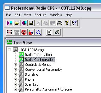
You can see the parameters of the radio and how it is currently configured by clicking on the various tabs under Tree View.
The ones you are most concerned with is "Radio Configuration", "Controls & Menus", and "Conventional Personality".
"Radio Configuration" Tab
At this point the only three tabs under Radio Configuration are "Accessory Pins", "Tx Power", and "Accessory Configuration".
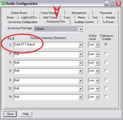
Click on the Accessory Pins tab and, using the drop-down arrow, select "Data PTT (Input)" for Pin # 3. All other Pin #'s are set at "Null". Click the "Close" button.
Next, click of the "Tx Power" tab.
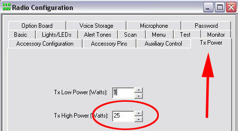
Here is where you set the transmit power level in Watts. We only use the "Tx High Power" setting. Since the radio has the ability to be configured to two transmit power settings (Hi and Low), you can set the "Tx Low Power" setting as well, if you choose. Like I mentioned, our club doesn't care about two power settings for a VARA FM gateway. One thing to keep in mind... if you have a very active gateway like we do and your power is fairly high, I would recommend adding additional cooling, like a fan, to keep the radio cool. A bracket to support a fan can be found on e-Bay HERE. When you are done, click the "Close" button.
Next, click the "Accessory Configuration" tab.
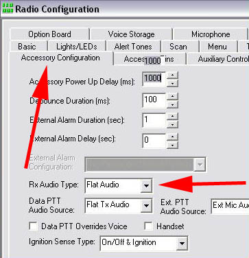
Using the drop-down arrow under "Rx Audio Type", select "Flat Audio". When you are done, click the "Close" button.
Back to "Tree View".
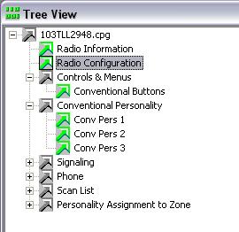
Next, click on "Controls & Configuration" followed by "Conventional Buttons".
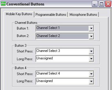
"Conventional Buttons" Tab
By default "Mobile Key Buttons" should be selected on opening. These allow you to set the four channel buttons on the front of the radio. You really only need "Button 1" for use as a gateway. We set "Button 2" to a different frequency from the primary (Button 1) for testing purposes, but not really necessary. Remember, when the radio auto-restarts it defaults to Channel 1, so Channel 2 won't do you much good in a remote gateway.
When you are done, click the "Close" button.
Next, click on the "Conventional Personality" tab followed by the"Conv Pers 1" tab. We are only concerned with Conventional Personality 1 since we only use Channel 1. You will have to set up the additional personalities if you want additional channels available. Remember, the radio defaults to Channel 1 upon restart.
"Conv Pers" Tab 1 to 4
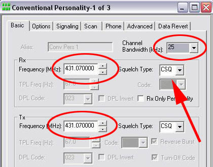
Under the "Basic" tab is where you will set the Receive and Transmit frequencies, the Channel Bandwidth, and the Squelch Type. Set your frequencies as appropriate. Most likely the Transmit and Receive frequencies will be the same for a VARA FM gateway. We also select frequencies in the lower portion of the UHF band because there seems to less interference to us in our area.
Also, select the appropriate Channel Bandwidth. We use WIDE band (25 KHz) for greater through-put with VARA FM. If your gateway is set up for WIDE, it will also accept NARROW, not just WIDE.
The Squelch Type should be CSQ (Carrier Squelch).
Under the "Options" tab is where you will select the transmit power level. You previously set the "High" and "Low" power levels in Watts. Now you have to decide which one you have to use.
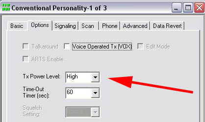
Most likely you will select "High" for "Tx Power Level", but you could select "Low" if you choose (why??). When you are done, click the "Close" button.
Be sure to SAVE your configuration (File -> Save or Save As).
You should now be able to program your radio. Select File -> Write Device once the radio is connected to your computer via the programming cable, and the radio powered on.
I would also recommend NOT transmitting until you have connected an appropriate dummy load.